Is the MFFT suitable for measuring resins containing substances such as graphite?
The MFFT90 can be used to measure the Minimum Film-Forming Temperature (MFFT) of resin products. Some of these products may contain materials like graphite, which can change how the resin looks or behaves during testing.
In most cases, products with graphite can still be tested with the MFFT90, but the following points should be kept in mind:
Visibility: The MFFT90 works by showing where the resin changes from a powdery or cracked surface to a smooth film. If the resin contains graphite or other dark/pigmented substances, it may be harder to see this change. Applying a thin, even layer can help improve visibility and scraping with a wooden spatula may help identifying the MFFT point easier.
Even Mixing: The graphite should be well mixed in the resin. If it forms lumps, the test results may not be accurate.
Instrument Surface: The surface of the MFFT90 is made of stainless steel. The resin and all added materials must be safe to use on this surface. If the resin is strong, we recommend using the aluminium foil on the test bed with glycerin to stick it down and improve heat transfer. At the end of test the foil can be removed.
Other Signs of Film Formation: If the film formation is hard to see, the user can also check by touching the surface gently to feel where the film has formed. Gloss changes can also help show where film formation begins.
If there are any doubts, a comparison test with and without graphite may help to understand how the material affects the film formation.
For many years a standard gloss meter has been specified and used as a Q.A. tool for quantifying and validating surface appearance quality. It is based on a long established measurement principle, this compares the amount of light transmitted onto a surface with the amount reflected from it at a fixed measurement angle. This produces a value of gloss unique to that surface. This gloss value, however, can often be misleading as it does not define other surface appearance effects that can be seen visually.
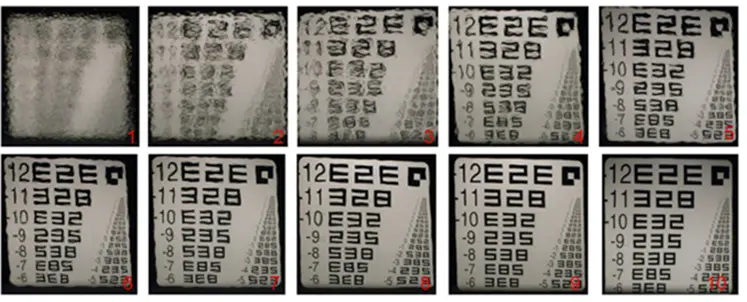
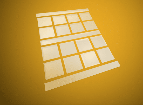
The ten panels above demonstrate this visual difference.
When measured using a standard gloss meter, each of the panels produces the same gloss value however to the eye they appear different.
This visual versus measured discrepancy is due to the texture being present on the surface caused by large (orange peel) and microscopic structures (haze).
Due to the limitations in measurement technology a gloss meter is, therefore, unable to detect these structures as it can only determine gloss values hence why visually the surfaces appear substandard.
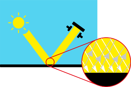
Gloss is the visual sensation associated with the perceived brightness of direct light reflected from a surface. A glossmeter measures the specular part of the reflection, so a matte surface can reflect a lot of light diffusely and still read low gloss.
Gloss meters quantify this effect by measuring the specular light reflection from a surface at an equal but opposite angle of illumination at defined angles.
Gloss Unit
The Gloss Unit (GU) is defined in international standards including ISO 2813 and ASTM D523. It is determined by the amount of reflected light from a glass standard of known refractive index.
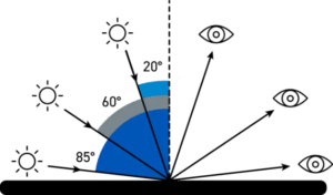
The measurement angles most commonly used for gloss are 20°, 60° and 85°.
The most appropriate angle should be selected dependent on the glossiness of the sample surface.
Using the correct measurement geometry increases resolution and improves the correlation of results with human perception of quality.
How to determine the best angle
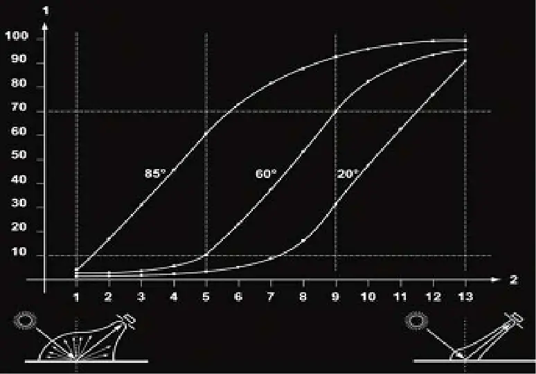
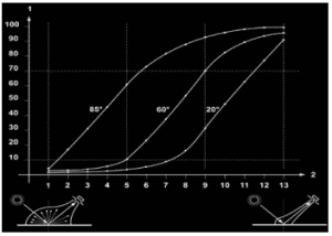
To determine the correct measurement angle the surface should be assessed with the 60° geometry-
Matt surfaces which measure below 10 GU @ 60°should be re-measured with the 85° angle.
High gloss surfaces which measure above 70 GU @ 60° should be assessed using the 20° angle.
The 60 degree angle is best suited to mid gloss measurement of samples between 10-70 GU.
On a matte surface the 60° gloss reading is low and small differences between samples are hard to resolve, so 85° is used. On a high gloss surface 60° readings are close together and small differences are hard to resolve, so 20° is used.
Law of Reflection
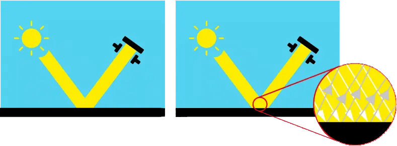
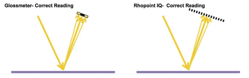
Law of reflection is the direction of incoming light and the direction of outgoing light reflected make the same angle with respect to the surface.
The standard method for measuring gloss using a gloss meter at 20° requires an acceptance angle of ± 0.9° around the specular angle of 20°.
This narrow angular measurement range of reflected light does not allow the sensor in a gloss meter to detect the texture on a surface as the structures within the texture cause the reflected light to be deflected at a greater angle.
Measuring Gloss with the Rhopoint IQ
The Rhopoint IQ is different to a gloss meter as it uses a linear diode array (LDA) at 20° to measure the distribution of reflected light between 12.75° – 27.25°.
Conventional glossmeter optics are used at 60° & 85° and these fully comply with international gloss standards such as ISO 2813 and ASTM 523.
The instrument does not have physical receiver apertures like a conventional gloss meter; the 20° gloss value is obtained by measuring with the elements of the linear array that correspond to the angles specified in the standards.
This feature allows the instrument to quantify the effects of texture on a surface that can be classified as either orange peel or haze according to their size.
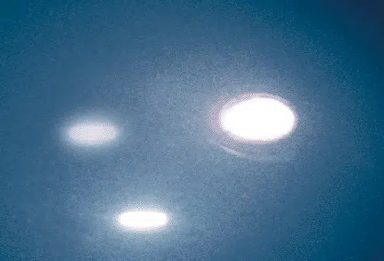
Haze is light that has been reflected by very small surface structures adjacent to the main specular angle. The term “Haze” defines the milky halo or bloom observed visually on high gloss surfaces.
Surface haze
Surface haze can be problematic in most coating applications including automotive manufacture, powder coatings and other high gloss coatings. It can be attributed to a number of causes including incompatible materials in a formulation, poor dispersion and problems encountered during drying/curing/stoving.
Coatings without haze can be seen to have a deep reflection and have high reflective contrast. Those with haze exhibit a slight “milky” finish which can be seen over the highly glossy surface.
Haze is caused by microscopic surface texture which diffuses light adjacent to the main component of the reflected light.
When viewing the reflection of a strong light source in a surface with high haze, the image “blooms” and has a bright halo around it.
Haze is an important measure for highly polished metals and is often associated with polishing marks and machining direction.
Measuring Haze with the Rhopoint IQ
Using the LDA technology in the Rhopoint IQ, measurement of Haze is easily achieved, using the procedure described in ASTM E430, by analysing the amount of light that has been deflected +/-2° either side of the specular angle.
Haze compensation is also included to allow haze measurement on different coloured surfaces, the light diffusion caused by bright colours e.g. white, yellow would otherwise produce higher levels of haze even though they are the same.
This measurement is performed automatically by the instrument in one process.
Distinctness of Image is, as the name implies a function of the sharpness of a reflected image in a coating surface.
Two surfaces finished with similar coatings may exhibit identical gloss values but visually the quality of one coating can be seen to be very poor. Upon closer inspection the visually substandard poor coating has a highly textured dimpled appearance known as “orange peel”. When a reflected object is viewed in such a coating the image becomes fuzzy and distorted.
What is orange peel?
Orange peel, waviness, texturing, pin holing and similar effects can be problematic in many high gloss coating applications including automotive, powder coating and any other industries that requires a smooth homogenous finish. All these effects can be measured with the Rhopoint IQ.
DOI has been measured instrumentally and subjectively in the automotive industry for many years. Instruments that measured this value in the past were bulky expensive and some had poor repeatability. DOI measurement was not common outside of automotive because of the cost of equipment was high and the demand for high quality gloss finish was not as crucial.
Measuring Orange Peel and Distinctness of Image (DOI) with the Rhopoint IQ
The Rhopoint IQ measures the DOI of a surface by quantifying the way a reflected measurement beam is spread and distorted around the specular angle.
Example test panels with low and high DOI values. Orange peel, texture, flow out and other key parameters can be assessed in coating applications where high gloss quality is becoming increasingly important.
The DOI value of a surface is a number between zero and one hundred; a surface that exhibits a perfect undistorted image returns a value of 100, as texture increases the image becomes distorted and the DOI value decreases.
Disadvantages of Distinctness of Image
Distinctness of Image (DOI) was one of the first parameters to define surface texture, it was originally a visual and instrumental measurement.
Distinctness of image is, as the name implies a function of the sharpness of a reflected image in a coating surface. As more orange peel becomes visible on a surface the distinctness of the reflected image becomes lower.
This effect is measured instrumentally by quantifying the way that light is reflected around the specular angle, a perfectly smooth surface with sharp reflection has a DOI of 100, decreasing with the amount of orange peel present.
Whilst the DOI parameter was suitable for the fineness of finish available around the time of its development, the quality of today’s coatings has increased to a point where DOI is a much less relevant measurement in many industries.
What is Reflected Image Quality (RIQ)?
Reflected Image Quality is a new measurement developed by Rhopoint Instruments to provide greater sensitivity when evaluating highly reflective coatings and the specular / diffuse element of lower gloss materials.
Two highly reflective surfaces that have very small changes in orange peel or texture will show very little or no change in DOI due to the way that it is calculated, but will appear quite different visually.
By reducing the sensing distance around the specular angle and measuring the reflected light and distortion around it, a much higher resolution response is achieved with greater linearity, more in line with the visual experience.
Two highly reflective panels with the same gloss values show little change in DOI but appear different. However, when using RIQ a greater differentiation is achieved.
Average measurements of ACT Panels 5 – 10 show little variation when using DOI.
The RIQ value of a surface is also a number between zero and one hundred; a surface that exhibits a perfect undistorted image returns a value of 100, as the values decrease higher surface texture is present and the image sharpness reduced.
DOI is not sensitive to low amounts of orange peel on the highest quality surfaces.
RIQ has more proportionate response to orange peel on a wider range of surface finishes.
RIQ works well in differentiating low gloss surfaces with different specular/diffuse components.
RIQ measurement is sensitive enough to quantify appearance differences due to-
Substrate alignment (horizontal/vertical)
Coating formulation
Substrate
Application technique
Gloss, Haze, DOI and RIQ values are all produced simultaneously in one fast measurement using the Rhopoint IQ.
In addition to this…Surface flatness also affects the reliability of measurements made with a glossmeter. Rhopoint IQ however incorporates Flatness compensation.
20° gloss & haze meters have fixed geometry. They require very flat surfaces to measure accurately.
The Rhopoint IQ uses a 512 element sensor that measures 20 +/- 7.25°. It mathematically determines the gloss angle.
With a standard gloss meter non-flat surfaces cause light to reflect on an incorrect part of the sensor and give inaccurate gloss results. With the Rhopoint IQ light is reflected on different areas of the diode array, and the instrument automatically compensates for the surface irregularities.
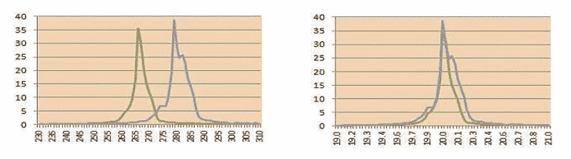
On the left: Two similar appearance surfaces, one is curved- the reflected light falls away from the centre of the array.
The reading on the right showing the IQ automatically compensating for non-flatness.
Law of Reflection: The direction of incoming light and the direction of outgoing light reflected make the same angle with respect to the surface.
RSpec is the peak reflectance measured over a very narrow angular band in the specular direction (+/-) 0.0991º.
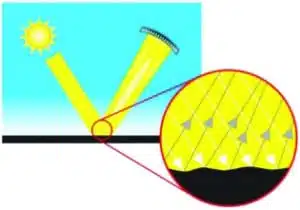
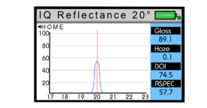
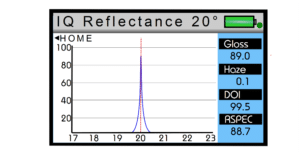
RSpec is very sensitive to any texture that is present on a surface. This texture or waviness acts as a concave or convex reflector that deflects light around the specular angle. When RSpec is equal to the gloss value the surface is smooth, as texture increases the RSpec value decreases.
The diagram above shows the same coating applied to two panels, the first has orange peel/waviness present due to the incorrect application setting on the spray gun.
The instrument should be calibrated before use. It should also be calibrated if there is a change in conditions (temperature, humidity, etc.) Generally, the calibration should be checked by taking a reading on the supplied standard at least every half-hour during continuous use.
We recommend that instruments are returned to Rhopoint or an accredited service centre on a yearly basis. Current generation instruments will remind you when the recalibration is due.
You can dismiss the warning that appears by pressing the centre button, and the instrument will function as normal. This message depends on the calibration date programmed into the instrument, which will match the calibration date declared on the certificate. The calibration is valid to 1 year from the date of calibration, or from the date of first use (if this has been filled in). After this, the instrument can be used for comparative use only. It cannot be used as part of a traceable process.
To remove dust, there is a cleaning cloth supplied. Take care to touch only one side of it and use the other side to clean the tile. This will help stop finger grease from building up over time. If a replacement cloth is required, you can contact an accredited service centre, or use a fresh cleaning cloth suitable for glasses.
If you suspect there is a greasy residue on the tile, breathe on it. Any grease will show up as a slight rainbow sheen. This can usually be removed with a fresh cleaning cloth. Iso-Propyl Alcohol can be used to remove larger amounts of grease. Ensure that the IPA is removed from the tile with a lint-free cloth while still wet. Allow the tile up to an hour to settle before use.
If available, dry, clean air from a compressor can be used to remove dust.
You will need to send both for a full calibration. The gloss meter must be used with a certified standard for traceable results. It has its linearity tested against NMI standards. The tile has a value assigned. When the instrument is calibrated on the provided tile, the results are traceable to our NMI certification in accordance with BS EN ISO 2813, which is the main standard for the measurement of gloss.
We do have a tile-only calibration option however, we would recommend that this is used only for additional tiles.
The first thing to check is the battery. Connect the instrument to a power source via the USB cable. A computer, or the supplied mains>USB converter will both work. Leave the instrument for 30s, and then try to power up again.
If the instrument beeps but the screen does not turn on, this indicates that there is an issue with the screen. This will require repair at a Rhopoint accredited service centre.
If the LED lights at the base of the instrument turn on when the power button is held, then the instrument is in programming mode. This will require repair at an accredited service centre.
There are three possible error messages that may result from a failed calibration.
“Warning! Possible calibration error”
This message appears when the results of a calibration do not match the stored one. If you have calibrated your instrument on a different tile from the normal one (such as a mid-gloss tile) you can safely ignore this message.
Check that the instrument is correctly seated on the calibration tile and that the protective white tissue supplied with the instrument has been removed.
Check the tile and optics for contaminants. A residue-less solvent such as Iso-Propyl Alcohol can be used to clean these surfaces.
“Warning! Possible contamination”
This message appears on instruments that have a haze measurement function when the haze is higher than expected. If you are calibrating on a low-gloss tile, this message can be safely ignored. If this is done regularly, “Haze Tolerance” in the calibration menu can be set higher.
Check the instrument is correctly seated on the calibration tile, and the white tissue supplied with the instrument has been removed.
Check the tile and optics for contaminants. A residue-less solvent such as Iso-Propyl Alcohol can be used to clean these surfaces.
“Calibration Reference not set”
This means that the stored calibration has been lost or corrupted. The only function of the instrument that it will affect is calibration error detection. This message can be dismissed and the instrument used as normal. This issue will be resolved as part of a standard annual recalibration with an accredited service centre.
The first thing to remember is that each gloss measurement angles has different sensitivities at different gloss values. The 60° angle is used for general-purpose measurements. The 20° angle is most sensitive at high gloss values, and the 85° angle is sensitive at low gloss values.
The next thing to consider is the physical stability of the instrument. Even a small rocking motion can produce large variations in the gloss reading.
The finish quality of the surface can have a large impact. Uneven colours or textures will add a random variation to the gloss measurements. The best way around this is to take several samples and average the results. The more variation in the surface, the more samples will be required for a repeatable measurement.
If the instrument is used in the wrong range, it can become oversaturated. This occurs when measurements on mirror-like surfaces (130+GU @60°) are taken using the black range. To get accurate results on a mirror-like surface, the range must be set mirror or auto in the measurement menu.
The first thing to try with an error is pressing the reset button. This is in a recess on the base of the instrument, near the serial number sticker.
Some versions of firmware will power off as soon as an error is encountered. This means that the fixes below will not be possible. In this case, the instrument will need to be returned to Rhopoint.
Code
Meaning
Cause
1
Cannot open config.ini
File system corrupt or Dataflash fault.
2
Cannot write config.ini
File system corrupt or Dataflash full.
3
Cannot read config.ini
File system corrupt.
4
Corrupt data config.ini
File data corrupt.
5
Cannot open calib**.dat
File system corrupt or Dataflash fault.
6
Cannot write calib**.dat
File system corrupt or Dataflash full.
7
Cannot read calib**.dat
File system corrupt.
8
Error saving data
Unable to create/write to results file. Dataflash full or faulty.
9
Error reading folders
File system fault, Dataflash probably corrupt.
10
RTC oscillator failure
Main board hardware failure.
11
Cannot create bstats.dat
Dataflash full or faulty.
12
Cannot open bstats.dat
File system corrupt or Dataflash fault.
13
Cannot write bstats.dat
File system corrupt or Dataflash full.
14
Cannot read bstats.dat
File system corrupt.
15
Cannot open sysdat.bin
Unable to open file – UC3B flash corrupt.
16
Cannot write sysdat.bin
File system corrupt or Dataflash full.
17
Cannot read sysdat.bin
File system corrupt.
18
Cannot open log.txt
File system corrupt or Dataflash fault.
19
Cannot write log.txt
File system corrupt or Dataflash full.
20
Cannot open cf.bin
File system corrupt or Dataflash fault.
21
Cannot write cf.bin
File system corrupt or Dataflash full.
22
Cannot read cf.bin
File system corrupt.
23
Scanner micro failure
Failure to connect to scanner.
24
Error saving stats data
Unable to create/write to stats.csv. Dataflash full or faulty.
25
Cannot open passfail.dat
File system corrupt or Dataflash fault.
26
Cannot write passfail.dat
File system corrupt or Dataflash full.
27
Cannot read passfail.dat
File system corrupt.
28
Corrupt data passfail.dat
File data corrupt.
29
Cannot open summary.csv
File system corrupt or Dataflash fault.
30
Cannot write summary.csv
File system corrupt or Dataflash full.
31
Cannot delete summary.csv
File system fault, Dataflash probably corrupt.
32
Undefined error
Main board hardware error.
Error codes 1-4
Delete config.ini:
Make a note/take a photo of the settings selected in the menu
Connect the instrument to the PC
Make sure hidden folders and system files are visible (control panel -> folder options -> view)
Navigate to the instrument (Computer -> IQ-METER)
Open the SYSTEM folder
Delete config.ini
Restart the instrument
Check to see if any settings have changed, put them back if required
Error code 2
Error code 2 can be caused by full memory.
Connect instrument to PC
Open DATA folder and back up any measurement data required
Select “Delete all batches” from the menu
Error codes 5-7
This error must be resolved by an accredited service agent.
Error code 8-14
Check to see if memory is full – if so, delete readings. They can be backed up and archived with a PC. If this problem persists, or the memory was not full, then the instrument must be returned to an accredited service agent.
Error code 15 – 17
For error code 16, make sure the memory is not full. If this does not resolve the error, then the instrument must be returned to an accredited service agent.
Error code 18 & 19
Connect the instrument to a PC via USB
Delete log.txt and restart the instrument
Error code 20 – 22
For error code 21, make sure the memory is not full. If this does not resolve the error, then the instrument must be returned to an accredited service agent.
Error code 23
First, press the reset button.
For instruments manufactured after June 2023, the following procedure should resolve the issue:
Ensure the instrument has at least some charge.
Power on the instrument.
Press the power button for one second, then release for one second. Repeat this at least 6 times. Please note – it can take up to ten times until the instrument switches off due to the timing and possible missed presses.
Switch off indicates the power reset procedure has been successful.
If the issue continues, please contact an accredited service agent.
Error code 24
The instrument must be returned to an accredited service agent.
Error codes 25 – 28
For error code 26, make sure the memory is not full. If this does not resolve the error, follow the rest of this procedure.
Make sure system files and hidden folders are visible (control panel -> folder options -> view)
Delete passfail.dat from the SYSTEM folder on the instrument
Restart the instrument and retest
Error codes 29 – 31
For error code 30, make sure the memory is not full. If this does not resolve the error, follow the rest of this procedure.
Back up the DATA folder if required
On the instrument select “Delete All Batches”
Restart the instrument
If the error is not resolved, then the instrument must be returned to an accredited service agent
Error code 32
The main board requires replacing – return to Rhopoint.
Measurement loops occur when the instrument cannot decide whether the surface it is measuring is a mirror or black gloss surface. The crossover is at ~130GU. In the measurement menu, “Range” can be set to “BLACK”, “MIRROR” or “AUTO”. If the sample you are measuring is in the crossover zone, try setting the range manually.
More recent versions of firmware handle switching between ranges better. You can contact an accredited service centre for details about whether there is a firmware upgrade available for your instrument.
This error can also be caused by calibration – if the black range is calibrated on a mirror surface, or vice versa, then this problem can occur. Enter the calibration menu, and make sure “Range” is set to “BLACK”, then calibrate the instrument on the supplied black tile. If a calibrated mirror tile is available, repeat this process for the mirror range.
In older versions of firmware, the instrument shut down after experiencing a fatal error. In this case, the instrument’s memory is usually full. Make sure you have backed up any important measurements to a computer with the USB connection. Switch the instrument on, and in the menu, select “Delete All Batches”.
If this does not resolve the issue, the instrument will require repair with an accredited service centre.
You can contact an accredited service centre for details about whether there is a firmware upgrade available for your instrument.
During power-up, the instrument takes an average of the input to each button to use as a baseline. This means that if your fingers or other conductive objects are near the buttons during power-up, it can affect their operation.
Minimum Film Forming Temperature ( MFFT ) is the lowest temperature at which a latex, emulsion or adhesive will uniformly coalesce when laid on a substrate as a thin film. An accurate MFFT value allows the formulation of products that cure correctly under specified application conditions.
Simply place the instrument on range one, allow the platen to stabilise and take note of the temperatures between point 1 and 10. Point 1 should read -5°C and point 10 should read 13°C There should be an even gradient between all points.
The instrument operation is governed by precision temperature sensors which are mounted on the reverse of the measurement platen. The output of these sensors is referenced to precision resistors which are extremely stable with time and different ambient conditions
It is because of this the instrument is completely self calibrating and regulating.
Yes, see table. 60 and 85 give greater resolution of measurement at these gloss levels (small visible differences in finish = a large difference in gloss value) Whilst 20 has a smaller measurement resolution, visible differences in gloss can be quantified with the Flex 20.
The measuring head should only be connected to the instrument for measuring larger flat surfaces. It is recommended to connect the instrument to the measuring head using cable for ease and stability of measurement.